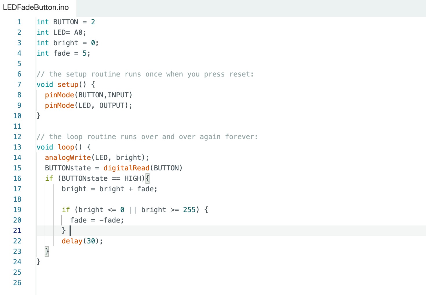
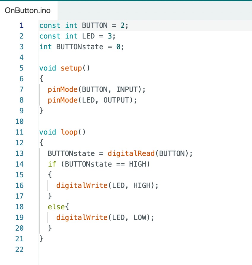
This week on embedded programming it go me excited to rev up for the final project push. This week I decided to build upon the idea of my week 4 board. During week 4 I made the button and LED in series meaning that the button when pressed would allow the LED to light, although this week I am putting the buttom on one digital pin, and the LED on another. I am doing this because I am going to use embedded programming to make the LED to some fun things. Using arduino code I am able to tell when the button is being pressed then, execute a script to control the LED.
Building the board
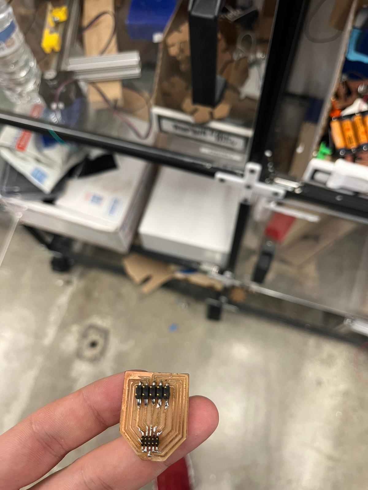
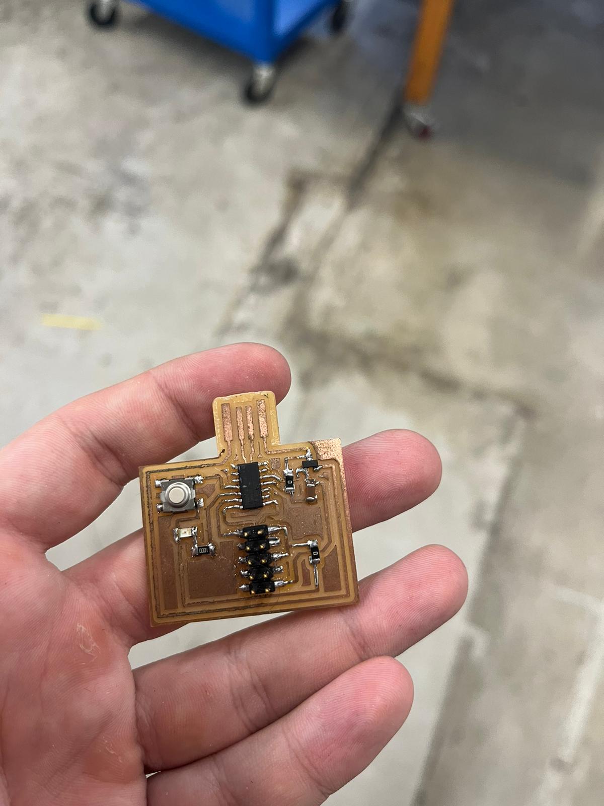
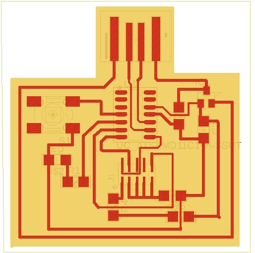
I took inspiration from my week 4 board, using the D11C as the chip. After putting importing all the components into my eagle schematic I tried to make the board. I tried to be as clever as possible with this board instead of copying what I had during week 4. A couple things I looked into were vias, and using different size airwires in order to make the board compact. This had varying degrees of success. For the vias I asked Rob about how that would work on a single sided board. The idea was that if I made a via like I normally would in the schematic, once the board was cut, I would be able to use a wire to connect the vias closing the loop. The reason I wanted to do that was to minimize the clutter of using 0 ohm resistors. The second tactic of changing the size of the airwires.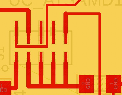
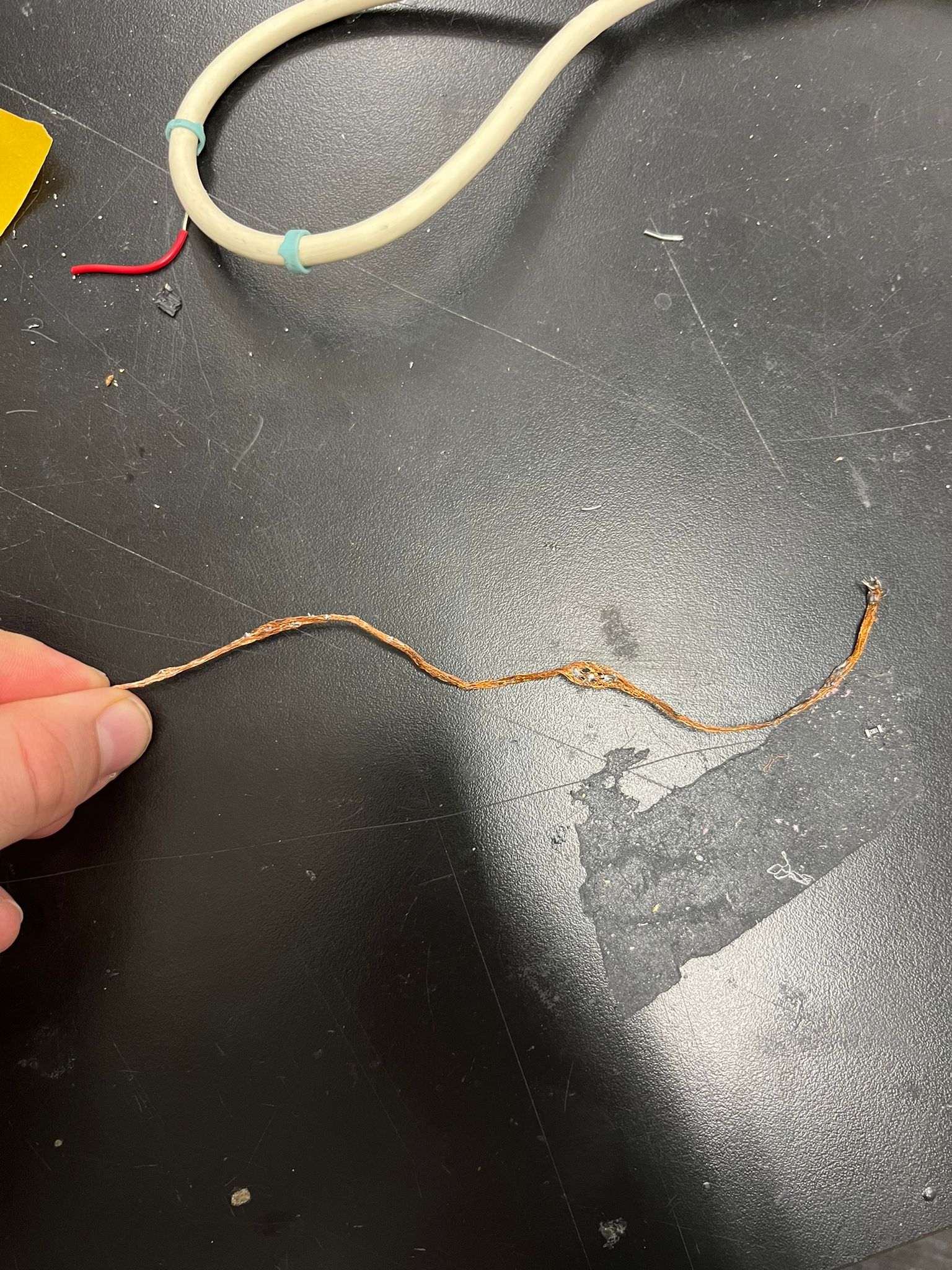
Braiding
This time when I was soldering the parts onto the board I made much fewer mistakes. And even when I did put more solder than I wanted, I was able to use the braid to remove the pieces skillfully.- Get a piece of the braid
- Put an unscathed part of the braid on top of the area which you want to take solder away
- Take solder iron and put it on the back of the braid to heat it up
- Lift away from the soldered area you want to remove from
Programming
In my schematic I used the wrong 5x2 pin header for my programmer. So I used Caine Ardayfio's genious idea of a converter between the two 5x2 pin headers.